Adapter Plate The last post covered the design of the adapter plate; this post covers the manufacture of it.
The plate starts life as a 10mm thick piece of mild steel sheet roughly 400 x 400mm. The profile is then cut with a water jet, these are a nice alternative to laser cutting in my experience, accuracy is dependent on the machine, but typically ±0.02mm I believe this also depends on the thickness of the part and hardness of the material.
In an earlier post I mentioned the accuracy of clutch alignment had to be <0.1mm, I will cover this later in the post, but remember 0.1mm for now.
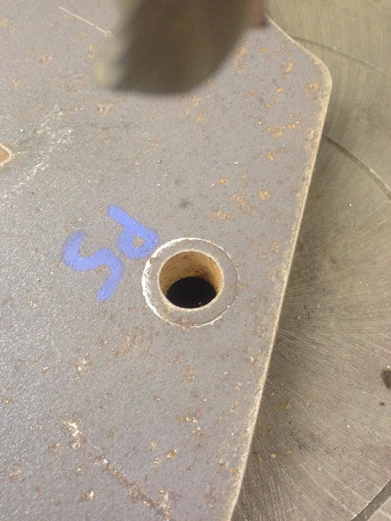
So, first job was to get the plate cut out, once profiled it looked something like this:
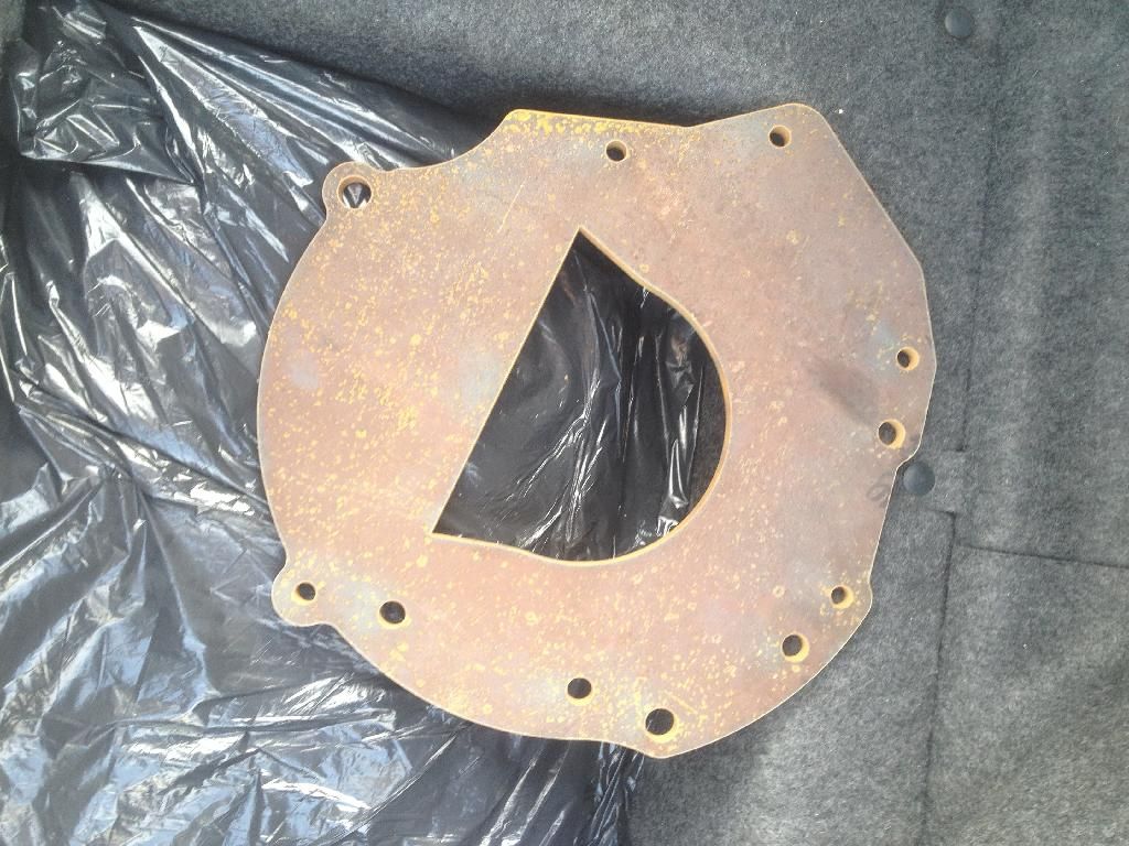
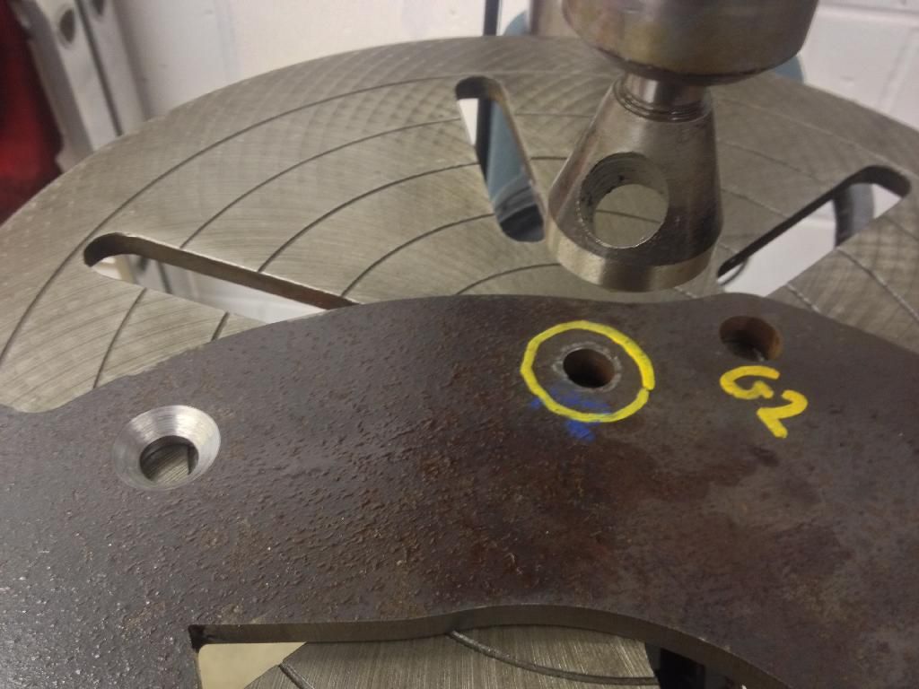
Fairly uninspiring, and not much use- the holes for the golf mounts have been sized for an M12 tap, hence the different sizes, Polo bolt pattern uses through bolts (bar one) so have clearance holes.
Staring at a drawing, lots of tea, and using the Polo spacer plate helped get things sorted in my head:
In my old unit I used to have a pillar drill, I’ve since moved and had to get rid. This was the perfect excuse for PPP to purchase a drill so I can make these adapter plates; I doubt the profits from adapter plates will ever payback the cost of the drill mind
 Drill Time
Axminster with a 16mm chuck (important):
So, first job is to bolt the plate down and start lining things up. (The first job was actually the laborious task of getting the drill perfectly level, bolting it to the concrete floor, greasing it all and rebuilding it after dismantling it to securely mount it, but that’s boring...)

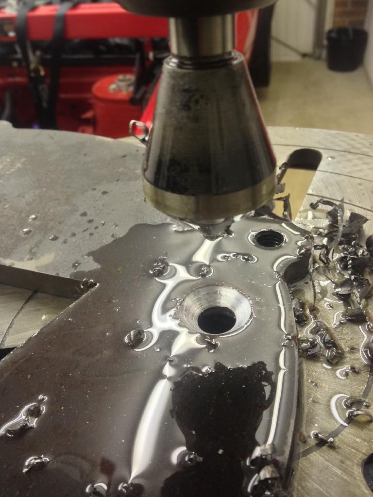
The drill is fitted with a conical shaped bit which allows a true center to be found. This is vital, we can assume the holes have been profiled accurately (±0.02mm) so the biggest inaccuracy comes from me setting the drill correctly.
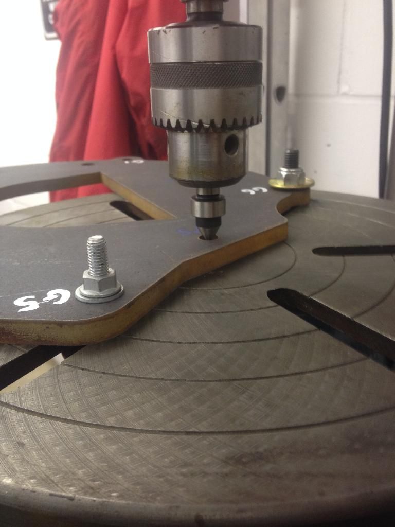
Once the center has been found (i.e. the headstock isn’t pushed in any direction when engaged with the hole) I then swapped to a 16mm slot drill for the dowels.
I lightly scored the plate and measured the witness marks and convinced myself I’d got everything true:
Time to make some swarf:
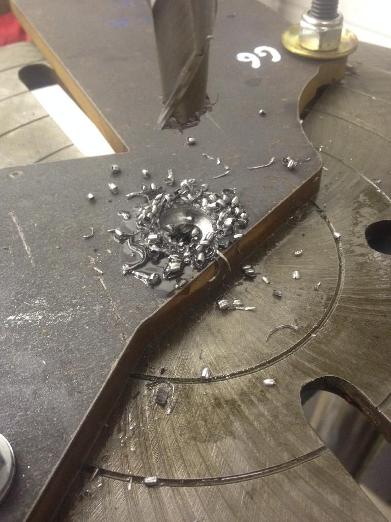
So, first hole cut. I wasn’t happy with the drill, upon measuring the hole it was 16.38mm (Dowel OD is 16.0mm) so the dowel was like a dick in a shirt sleeve. The drill was chattering slightly, I decided to reduce the drill speed, use a different oil (0w40 fully synthetic from the other half’s car) and not be such a wimp.
First Hole with dowel:

Not good!
Second hole with revised cutting speed, lubrication and a little more pressure resulted in 16.09mm, result!
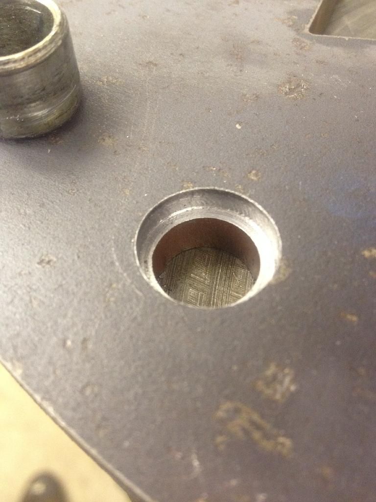
Second hole with dowel fitted:
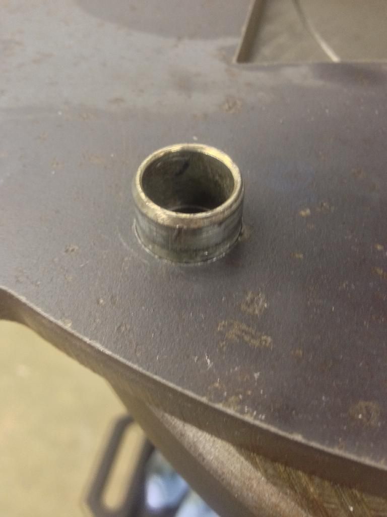
At this point I decided to measure various boxes I had laying around, I expected bang on 16.0mm from each, I was wrong. 16.08mm to 16.23mm- now some of my boxes have been on and off multiple times, but it was encouraging to know I could get the tolerance towards the tighter end of the spectrum. So, my target of <0.1mm from earlier was looking possible. I have no way of measuring this in an installed position, so I can only go from dowel locations.
My tolerance stack is 0.09mm on the two Polo dowel holes, and 0.02mm on the Golf dowel holes. Although I’m using the holes which had been profiled to locate my center find in, so assume I can get a Polo dowel to 0.11mm and a Golf dowel to 0.02mm. So not quite the <0.1mm original target, but without a milling machine I can’t get this any better, plus it’s an improvement over some of my stock gearboxes!
Onwards!
Countersink The plate bolts to the Polo block, this dictates the face must have countersunk fasteners, I used an A2 grade stainless M12 countersunk bolt. Quick check of the DIN/ISO standard gave me the angle of the countersink bit I needed to order (they’re usually 90° but worth checking).
So big countersink bit arrived, these are known as snail shells apparently, they don’t chatter and I've been really impressed with it, leaves a nice finish and swarf is easily moved.
This process is the same as the slot drill, fit the center find, adjust, clamp the piece down, check, recheck, measure, adjust etc. Then countersink until the bolt fits flush!
All the bolts holes requiring a thread are then tapped- I used the pillar drill to start them all off, ensuring the thread was perfectly square, worked a treat!
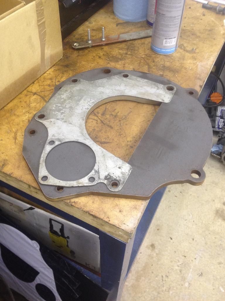
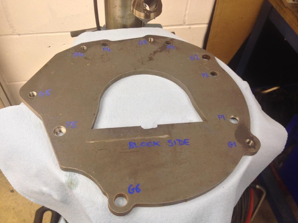
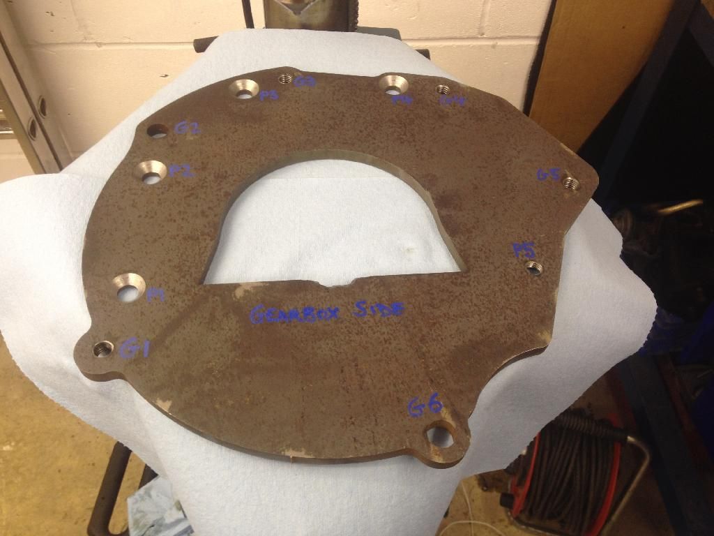
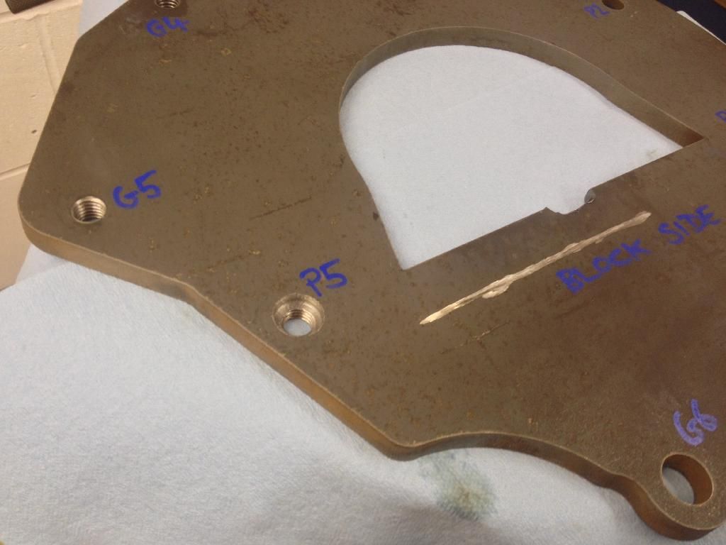
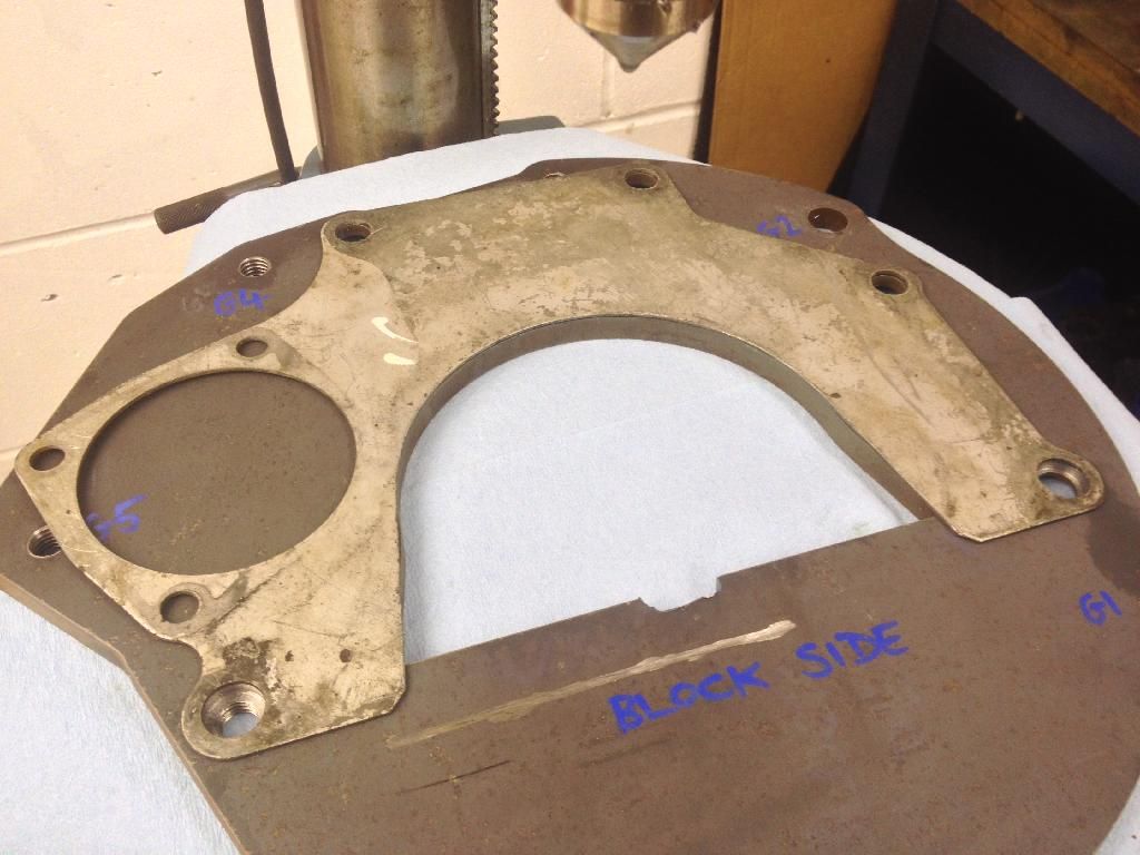
Post Machining Quick clean up and the plate looked like this (both sides shown):
You’ll notice there’s a mark from a grinder- for some reason I’d cocked up the measurement of the crank end oil seal housing. Bit of a pain, but it can be removed for mockup and the design revised before the next iteration.
Few more close ups:
 Dry Build
Once I’d done some measuring and checked the plate was straight and true, I then bolted it onto the Polo block. It is necessary to keep the standard plate so the dowel engagement is correct.
Looks something like this:
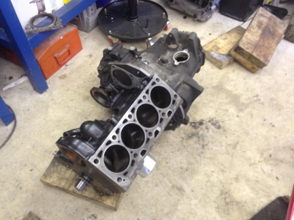
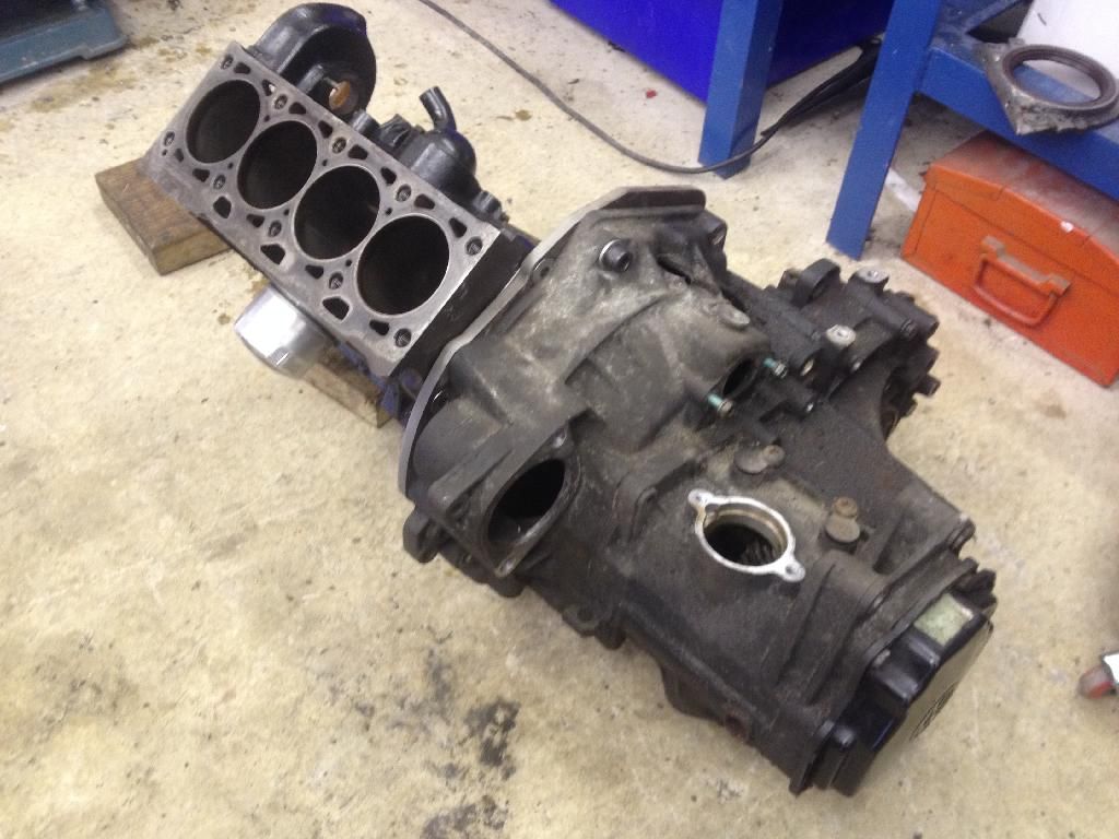
When bolted up the gearbox starts to look fairly large! You can also see the engine canted over to accommodate the driveshaft and output shaft clearance.
In the next update I’ll go over chassis modifications, cutting big holes out the leg, and hammering a square peg in a round hole. Although it will be fairly boring as it’s me making lots of measurements and swearing. I did get to play with my grinder though.
Cheers
Pete